
A converter can pass a protocol test and still deliver the wrong operational picture. Choosing an m-bus to modbus converter means checking more than protocol labels: meter compatibility, data mapping, and how the wider control system will read each value all matter.
A gateway bridges M-Bus meters and a Modbus-based system by polling meters and exposing their data through Modbus registers. Incomplete mappings or mismatched configurations can leave operators with missing or misleading readings. The right solution depends on the full metering architecture, not just the connection between two protocols.
This guide explains where conversion fits, what to assess for device and register compatibility, and how to identify installation and integration risks. It also compares a standalone converter with an integrated gateway approach, so you can judge which better supports your monitoring and operational systems. NET WIZARDS supplies an M-Bus / Modbus Gateway alongside industrial networking equipment and metering solutions, helping connect metering data with systems that support operational efficiency and energy optimization.
Key Takeaways
- Evaluate an m-bus to modbus converter by the meter data it needs to acquire and the way the receiving system expects to read it.
- Separate protocol conversion from measurement: the gateway transfers and represents meter data, but it doesn’t change what the meter measures.
- Compare standalone converters and integrated gateways by their role, integration boundary, and system ownership.
- Reduce integration risk by defining required data points, documenting register mappings, and validating readings end to end.
- Consider how an M-Bus / Modbus Gateway fits within a wider industrial integration architecture and supports access to metering data for monitoring and operational decisions.
Table of Contents
What an M-Bus to Modbus Converter Does in a Metering System
An m-bus to modbus converter is an interface that collects data from M-Bus meters and makes selected values available to a Modbus-based system. It translates communication and data representation so systems using different protocols can exchange readings. It doesn’t change the quantity a meter measures: a water meter still measures water, and an electricity meter still measures electricity.
How M-Bus and Modbus serve different roles
M-Bus is designed for communication with utility meters, allowing a system to collect readings from devices such as water, heat, and electricity meters. The M-Bus (Meter-Bus) standard provides background on its role in meter reading. Modbus serves a broader industrial role, carrying data between devices and monitoring or control systems.
Because the protocols represent and exchange data differently, a system needs an intentional interface between them. The converter interprets meter responses and maps relevant values into a format the Modbus side can access. A protocol label alone doesn’t establish that the receiving application will get the correct reading in a usable form.
Where the converter sits in the data path
Featured snippet definition: An M-Bus to Modbus converter is a gateway that reads data from M-Bus meters, maps selected values, and exposes them to a Modbus-based system.
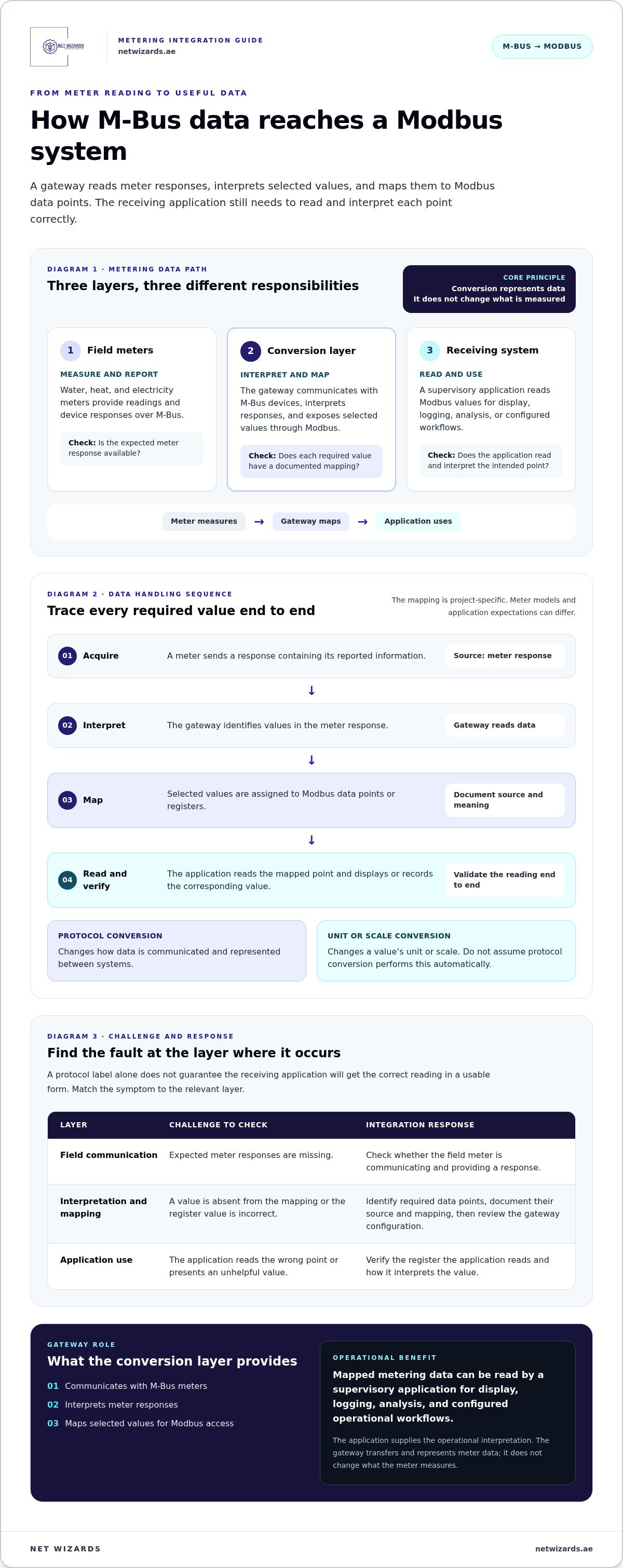
The field meter measures and reports. The converter or gateway communicates with the M-Bus devices, interprets their responses, and presents mapped values through its Modbus interface. A supervisory application, such as a building or industrial monitoring system, reads those values for display, logging, analysis, or operational workflows. The application determines how the data informs decisions; the converter doesn’t perform that operational interpretation.
Metering data path
Field meters
M-Bus readings and device responses
↓
Conversion layer
Communicates with meters, interprets responses, maps values
↓
Receiving system
Reads Modbus data for monitoring or control applications
This architecture separates three concerns that are easy to conflate:
- Communication transport: The physical connection carries messages between meters, gateway, and receiving system.
- Protocol interpretation: The gateway understands M-Bus responses and makes configured data available through Modbus.
- Application-level use: The supervisory system assigns operational meaning to readings, such as displaying consumption or recording values for analysis.
For example, a gateway may expose a meter reading through a Modbus register, but the receiving application still needs to know what that register represents and how to interpret its value. Clear ownership of each layer helps teams locate faults: missing meter responses point toward field communication, incorrect register values toward interpretation or mapping, and unhelpful displays toward application configuration. This division provides a practical basis for the integration checks covered later in the guide.
How M-Bus to Modbus Conversion Handles Meter Data
Reliable integration depends on what happens to each reading after a meter sends it. A gateway acquires a meter response, interprets its data, maps selected values to Modbus data points, and makes those points available to the receiving system. The official M-Bus standard information provides technical context for the meter-side protocol, while the values an application receives depend on the meter and project configuration.
From meter response to Modbus data point
Start by identifying the information the application actually needs, such as a consumption reading or another value provided by the meter. Trace each required value back to its source in the meter response. The gateway interprets that response and associates selected values with Modbus data points or registers. The receiving application reads those mapped points for monitoring, reporting, or another configured function.
This mapping is project-specific. Meter models may expose different information or represent data differently, while the supervisory system has its own expectations for data type, meaning, and presentation. Document the source and intended use of each value so the mapping can be reviewed during commissioning and future maintenance.
Meter data flow and validation
Acquire: meter sends a response
↓
Interpret: gateway identifies the reported values
↓
Map: selected values are assigned to Modbus data points
↓
Read and verify: application displays or records the corresponding values
Protocol conversion changes how data is communicated and represented between systems. Engineering-unit conversion changes a value’s scale or unit, such as converting one unit of measurement to another. Don’t assume protocol conversion automatically performs unit conversion. Define any required scaling or unit treatment in the project mapping.
What conversion does not automatically guarantee
A gateway doesn’t necessarily expose every value available from a meter. A value can be present in a meter response but absent from the configured mapping, or mapped correctly while the receiving application reads the wrong point or interprets it incorrectly. These are distinct failure paths, so confirming that communication is active isn’t enough.
Use an end-to-end check for each required data point:
- Confirm the meter reports the required value and identify its source in the response.
- Record how the gateway maps that value, including its intended meaning and any required scaling or unit handling.
- Verify the Modbus point in the receiving application and compare its displayed or recorded value with the meter reading.
This process exposes mismatched formats before they lead to misleading dashboards or reports. It also avoids assuming universal compatibility: meter responses, gateway mappings, and Modbus implementations must fit the specific integration. NET WIZARDS’ M-Bus / Modbus Gateway supports projects that need to connect metering data with Modbus-based systems. Define the required readings and validation steps as part of the integration scope.
Compare Converter Architectures and Selection Criteria
Choose an architecture by the work the integration must perform, not by the protocol names printed on a device. A dedicated converter provides a focused boundary between a defined M-Bus metering network and a Modbus system. An integrated gateway may fit better when the project requires metering data to connect with wider industrial systems. Neither option is universally superior. Ownership, visibility, and project scope determine the fit.
For the Modbus side, define how the receiving controller or application expects to communicate and consume data. The Modbus protocol details provide reference material on its protocol and implementations, but project compatibility still depends on the specific interfaces and configuration involved.
Dedicated converter or integrated gateway?
A dedicated converter suits a defined conversion task when the metering interface and receiving system have clear boundaries. Keeping the translation function distinct can simplify ownership and fault isolation. A broader gateway architecture may fit projects that connect metering to additional industrial systems. Compare how each design affects maintenance, visibility, and responsibility for data beyond the conversion point.
Architecture comparison
Dedicated converter
Project role: focused protocol interface
Integration boundary: between meters and Modbus system
Ownership focus: conversion and mapped data
Integrated gateway
Project role: broader system integration
Integration boundary: may extend beyond the meter-to-Modbus link
Ownership focus: gateway functions and connected applications
Selection outcome
Choose based on defined requirements, interfaces, and operational responsibility, not assumed device capabilities.
This comparison is a framework, not a claim that every device in either category has the same functions. Record the required role and boundaries in the project design. A standalone m-bus to modbus converter can suit a clearly defined interface need; a broader solution can support a wider architecture when the project calls for it.
Questions that expose integration fit
Before selection, build a requirements record that separates established facts from assumptions. This prevents a protocol label from standing in for evidence that the complete data path will work as intended.
- Meter side: Which meter models and M-Bus variants are in scope, and which readings must the system use?
- Data requirements: What does each reading represent? Does the application require particular units, scaling, status information, or update behavior?
- Modbus side: What interface and data points does the receiving system expect, and how will it identify and interpret them?
- Operational ownership: Which system handles interpretation, monitoring, reporting, and alarm handling?
- Validation: Which assumptions need confirmation through configuration review and end-to-end testing?
Separate confirmed requirements, such as documented meter models or application interfaces, from assumptions. Then evaluate each architecture against the same record. This makes trade-offs visible, supports maintainable system ownership, and reduces the risk of selecting a solution that communicates successfully but doesn’t deliver the readings or visibility the operation requires.
Resolve Common M-Bus to Modbus Integration Challenges
A live connection doesn’t prove that a metering integration is complete. The system may communicate while readings remain absent, misinterpreted, or unavailable where operators expect to use them. A disciplined commissioning process traces values from the meter response through the conversion layer to the receiving application, then records what has been tested and who owns each part.
Diagnose missing or inconsistent meter values
When a reading is missing or unexpected, trace it in sequence: check whether the meter provides the required value, whether the gateway receives and maps it, and whether the application reads and interprets the mapped point correctly. Compare the expected reading with what the conversion layer exposes. Record mapping changes and test results so later maintenance starts from an accurate integration record.
Different symptoms point to different checks. An absent value may indicate an unmet data requirement or a gap in the mapping. An incorrect value may reflect interpretation or scaling differences. Data available at the gateway but missing from a dashboard can indicate an application-side configuration issue. Avoid changing multiple layers at once. Isolate the point of divergence, correct it, and repeat the end-to-end check.
- Incomplete readings: Confirm that each required meter value is identified and included in the integration requirements.
- Mismatched interpretation: Document what each mapped point represents, including any agreed unit or scaling treatment.
- Disconnected application expectations: Align the application’s data points and display or reporting requirements with the gateway mapping.
For an m-bus to modbus converter, a mapping record should identify the meter value, the corresponding Modbus point, its intended meaning, and the validation outcome. This gives operations and engineering teams a shared reference rather than relying on individual assumptions.
Plan validation before operational handover
Agree with system stakeholders which readings matter and how the receiving application will use them. Test representative values across the full path, from meter through gateway to application. Record exceptions, unresolved assumptions, and the owner responsible for application-side interpretation or alarm handling. A clear handover supports operational visibility by showing where data is acquired, mapped, consumed, and maintained.
Commissioning flow
Review requirements → Confirm meter values → Document mappings → Validate readings end to end → Record exceptions and owners → Operational handover
At each stage: retain the expected result, observed result, and any action required before acceptance.
Monitoring should continue after handover. If a reading changes, disappears, or no longer matches application expectations, the documented path helps teams identify whether the issue sits with meter communication, gateway mapping, or the consuming system. This ownership model improves fault isolation and keeps operational teams informed without treating the gateway as the owner of every downstream application decision.
How NET WIZARDS Supports M-Bus and Modbus Integration
NET WIZARDS supplies Industrial IoT sensors, gateways, and protocol converters, including an M-Bus / Modbus Gateway for projects that connect metering data with Modbus-based systems. The gateway forms part of an integration architecture. Meter types, required readings, data mapping, and the receiving application all shape how the solution fits into operations.
Relevant engineering and integration capabilities
NET WIZARDS approaches the gateway as one layer in a wider industrial system. Project design can define where meter communication ends, how values are represented for the Modbus side, and which connected system owns monitoring and operational use. Clear integration boundaries give engineering and operations teams a defined basis for reviewing data flow.
NET WIZARDS provides M-Bus and Modbus gateway hardware alongside Industry 4.0 systems and specialized IoT connectivity solutions. Its AMI sub-metering systems and industrial networking equipment can form part of broader metering and monitoring architectures. Define the gateway’s role alongside the meters, receiving systems, and data responsibilities so the integration supports the project’s actual requirements.
Where a project needs broader monitoring and integration, the Industrial-grade IoT Cloud Platform can form part of the wider solution. Connecting metering data with industrial systems can support operational visibility and provide information for energy optimization. The value depends on project configuration and how teams use the data; integration alone doesn’t guarantee a particular operational result.
Define the next step for a project
A productive design discussion starts with the system facts. Bring the meter models and protocol details, the readings required by operations, the Modbus interface expectations, and the receiving application’s intended use. Identify who owns data interpretation, monitoring, and alarms. Separate documented requirements from assumptions that need engineering validation.
- Meters: identify the device types and the meter-side communication requirements.
- Data: specify required values, their meaning, and any unit or scaling expectations.
- Modbus system: document interface and data-point expectations for the receiving equipment or application.
- Integration boundary: clarify which system manages mapping, monitoring, and operational response.
This information helps define the mapping scope and plan end-to-end validation for an m-bus to modbus converter. Contact NET WIZARDS to discuss an M-Bus / Modbus Gateway integration around your meters, data, Modbus system, and operational objectives.
Set a Clear Path for Meter Integration
Treat the interface as part of the system’s long-term operating design. Record who owns the meter data, how the receiving application uses it, and how changes to meters or monitoring requirements will be assessed. That decision record gives engineering and operations teams a shared reference as the installation evolves.
NET WIZARDS brings 20 years in business to industrial integration work, including its M-Bus / Modbus Gateway. A project discussion can focus on the architecture your operation needs, rather than selecting an m-bus to modbus converter by protocol label alone. Define the system boundary, establish data responsibilities, and make the integration serve wider operational priorities.
A well-defined interface creates a stronger foundation for connected metering and informed operational decisions. Contact NET WIZARDS to discuss your M-Bus and Modbus integration requirements.
Frequently Asked Questions
Can an M-Bus meter communicate directly with a Modbus system?
Usually, no. A Modbus controller doesn’t inherently parse an M-Bus response, so an m-bus to modbus converter is generally needed to provide an interface. For example, a building system reading water consumption over Modbus needs the meter value represented in a way its driver can read. The arrangement depends on the meter, controller, and required data. Test the value in the target application, not only at the gateway.
Does an M-Bus to Modbus converter change meter readings or units?
No. A converter handles communication and data presentation; don’t assume it recalculates a measured quantity. If a dashboard expects water consumption in cubic metres but the meter or mapping presents another scale, establish which component applies any required conversion. Record the unit and intended meaning for each point, then compare a sample shown in the application against the meter’s own display.
Can one converter connect different M-Bus meter models?
Possibly, but a shared protocol label doesn’t establish that different models expose the same readings or interpret responses identically. Compatibility depends on the meters, the converter’s supported communication and data interpretation, and project configuration. For a site with several meter models, list each model and its required values, then test a representative reading from each type through to the receiving application before handover.
What information should be mapped from an M-Bus meter to Modbus?
Map the values that support a defined operational task. A facilities dashboard may need consumption totals, while an energy review may also require interval or status information if the meter and system provide it. For each point, record its source meter, meaning, expected unit, intended use, and receiving-system destination. This helps application teams distinguish similar-looking values and keeps dashboards and reports aligned with operational needs.
What causes missing readings after M-Bus to Modbus integration?
Common causes include a meter that isn’t responding, a gateway that doesn’t expose the required point, a mapping mismatch, or an application polling a different data point than intended. Compare the meter’s available reading, the value exposed by the gateway, and the application display. If the gateway value is correct but the screen is not, investigate the Modbus-side point configuration before changing meter settings.
Is an M-Bus to Modbus converter the same as a Modbus TCP to RTU gateway?
No. An M-Bus to Modbus converter bridges meter-side M-Bus communication to a Modbus system. A Modbus TCP-to-RTU gateway connects TCP/IP Modbus communication with serial Modbus RTU; it doesn’t, by that function alone, interpret M-Bus meter responses. A project may need to address both interfaces, depending on its equipment. For the separate TCP-to-RTU architecture, see the Modbus TCP to RTU Gateway: A Practical Integration Guide.
Can converted meter data be used in an industrial cloud platform?
Yes, as part of a designed integration, not simply because a converter is installed. The project needs a defined path from gateway to platform, including network connectivity, data ingestion, and how values will be identified for dashboards or analysis. NET WIZARDS provides an Industrial-grade IoT Cloud Platform for industrial monitoring and integration architectures. Define and validate the complete data path during design rather than inferring cloud access from protocol conversion alone.