
A TCP client can connect to a gateway and still read the wrong register, address the wrong device, or lose communication altogether. A modbus tcp to rtu gateway bridges Ethernet-based Modbus TCP systems and serial Modbus RTU devices, but reliable data exchange depends on more than connecting the cables. The gateway must route requests correctly, and the device address, register map, and serial settings must match the equipment.
Modbus TCP communicates over Ethernet, while Modbus RTU uses a serial link with its own timing and bus requirements. This guide explains the gateway’s role and how data travels between the network client and RTU device. It also provides a practical sequence for planning the integration, configuring device IDs and register references, matching serial parameters, and testing communication end to end. You’ll find ways to isolate common faults, including wiring issues, termination, timeouts, and mismatched settings. NET WIZARDS L.L.C supplies Industrial IoT sensors, gateways, and protocol converters, including M-Bus / Modbus Gateway solutions for industrial connectivity.
Key Takeaways
- A modbus tcp to rtu gateway relays requests between Ethernet-based clients and serial devices, then returns device responses to the TCP system.
- Document TCP and RTU requirements, register references, and operating conditions before configuring the gateway. Record unknowns rather than relying on assumptions.
- Follow a controlled sequence: document endpoints, configure the gateway, connect devices, and test representative data to identify faults methodically.
- When communication fails, check addressing, serial settings, wiring, and data mapping. Identifying the cause helps improve data accuracy and communication reliability.
- NET WIZARDS L.L.C’s M-Bus / Modbus Gateway offering is part of a broader industrial connectivity range that includes Industrial IoT sensors, gateways, and protocol converters.
Table of Contents
Why Use a Modbus TCP to RTU Gateway in an Industrial System?
An Ethernet-based PLC or SCADA system may need data from a sensor, meter, or controller that communicates over a serial Modbus network. Because the systems use different communication methods, they need an intermediary to exchange requests and responses. A modbus tcp to rtu gateway provides that link, allowing a TCP-side client to communicate with RTU-side equipment.
The gateway handles protocol communication, not the meaning of the application data. It can relay a request and return a response, but it cannot determine whether the client selected the correct device address, register, or data interpretation. Those details depend on the connected equipment and system configuration. Treat the gateway as one part of the integration, alongside correct addressing, register definitions, and verification.
What the gateway does between TCP and RTU networks
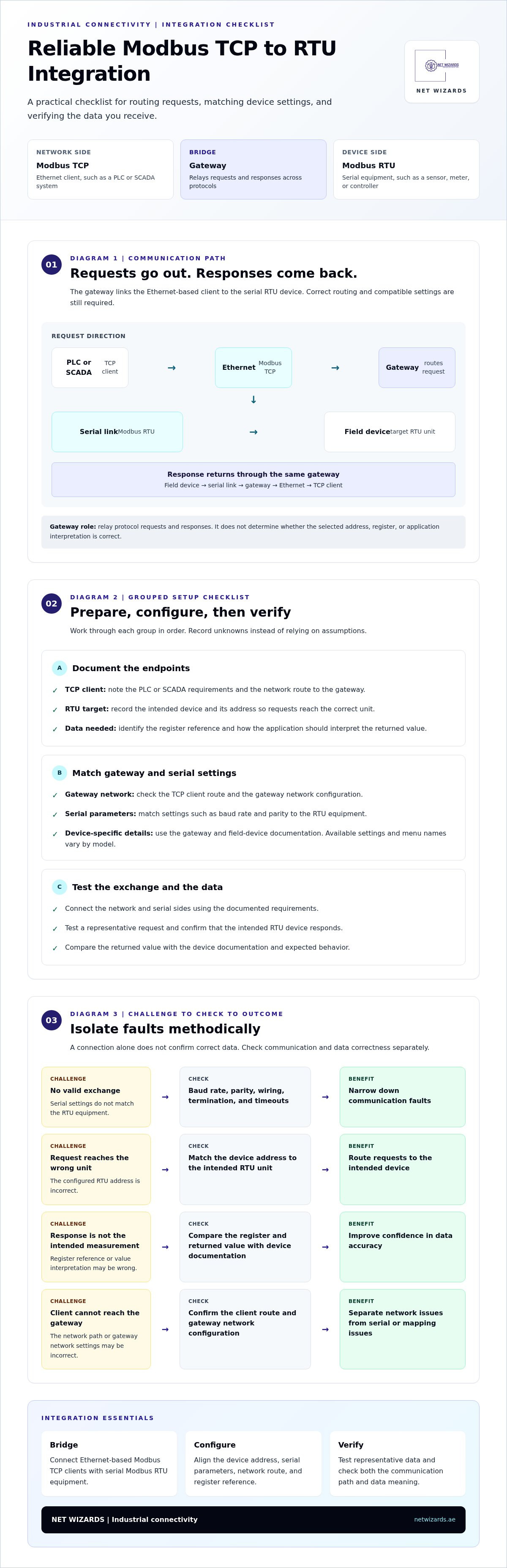
On the Ethernet side, a PLC or SCADA system acts as a Modbus TCP client and sends a request over the network. The gateway receives the request and communicates with the target Modbus RTU device over a serial link. The device returns its response through the gateway to the TCP-side client. This bridges two communication methods within one industrial system. For background on the Modbus protocol, including its TCP and RTU forms, see the protocol overview.
Diagram 1. Request and response path
PLC or SCADA (Modbus TCP client) → Ethernet → Gateway → Serial link → Field device (Modbus RTU)
Response path: PLC or SCADA ← Ethernet ← Gateway ← Serial link ← Field device
Integration challenges the gateway is intended to address
The central challenge is protocol mismatch, not a defect in either device. Ethernet and serial communication use different transmission methods, and the gateway provides the intermediary needed to exchange Modbus requests and responses. The connected devices still need compatible settings. An incorrect RTU address can direct a request to the wrong unit, while mismatched baud rate, parity, or other serial parameters can prevent a valid exchange.
Data interpretation adds another challenge. The client application must request the correct register and understand the returned value according to the field device’s documentation. A successful connection alone does not prove that the application is reading the intended measurement. Check connectivity and data correctness separately.
Use explicit configuration followed by systematic testing to address these issues. Record the TCP client’s requirements, the RTU device address and serial settings, and the register details the application needs. Mark undocumented items as unknown rather than filling gaps with assumptions. Then test a representative request and compare the returned value with the device’s documentation and expected behavior. This helps identify whether a fault lies in the network path, serial configuration, addressing, or data mapping.
How Modbus TCP to RTU Gateway Conversion Works
Conversion follows a request-and-response path. A supervisory system sends a Modbus TCP request over Ethernet. The gateway passes the corresponding request to a selected Modbus RTU device over the serial link, and the device’s response returns through the gateway to the original client. The gateway coordinates communication across the two protocol environments, but it does not determine whether the requested data point has the intended meaning in the application.
How a request travels across the gateway
Consider a supervisory system requesting a measurement from a field instrument. The client specifies the operation and data reference. The gateway receives the request through its TCP interface, identifies the target RTU device, and sends the request using the configured serial settings. The RTU device processes the request and replies, and the gateway relays the response to the TCP-side client.
The exchange depends on a configured path through both interfaces. The TCP side needs a network connection to the gateway and a route from the client. The serial side needs the correct device selection and settings that match the RTU network. Available settings and menu names vary by gateway model, so use the relevant device documentation rather than assuming every interface works alike.
Diagram 2. Request and response across protocol boundaries
Request: TCP client → Ethernet / Modbus TCP → Gateway [network context and RTU device configuration] → Serial link / Modbus RTU → Field device
Response: TCP client ← Ethernet / Modbus TCP ← Gateway [receives and relays response] ← Serial link / Modbus RTU ← Field device
Configuration points: TCP client route and gateway network settings | RTU device selection and serial settings | register reference and application interpretation
The serial side has its own communication behavior and device requirements. An overview of Modbus RTU in industrial automation explains the role of RTU communication in equipment networks and why a gateway is needed to bridge it with TCP.
Addressing, register references, and data interpretation
Correct routing begins by identifying the intended RTU device and matching its identity to the gateway configuration. The TCP client’s request must reach that device, not another unit on the serial network. The requested register reference must also match the equipment documentation. A connection can succeed while returning the wrong point if the device address or register reference is inconsistent.
Protocol transport and application meaning are separate. Modbus carries a request and response; the equipment documentation defines what a register represents and how its value is formatted. For example, a register may represent a measured process value, but the client must interpret it according to the instrument’s documentation. The gateway does not infer that meaning.
Before commissioning, document the client request, intended RTU device, register reference, and expected interpretation. Compare each item with the device documentation, then test a representative read and verify the result in the application. This makes faults easier to isolate and reduces the risk of treating successful communication as proof of correct data. For gateway integration requirements, the NET WIZARDS L.L.C contact page provides a way to discuss the communication path.
What to Check Before Selecting or Configuring a Modbus Gateway
A gateway may support the required protocol conversion but still fail to meet an application’s needs if the endpoints expect different settings or data references. Before selecting or configuring a modbus tcp to rtu gateway, compare the TCP client, serial devices, register requirements, and installation environment. Separate confirmed facts from assumptions so unresolved compatibility questions are visible before setup.
Comparison framework: record each requirement and its status
TCP-side requirements: Client or supervisory system, network connection details, and how the client will address the gateway. Record documented values as confirmed and mark unverified network details as unknown.
RTU-side requirements: Device identity and communication settings stated in the equipment documentation. Treat undocumented or assumed settings as unresolved.
Data mapping: Register references, data types, and required read or write operations. Note differences between the device register map and the application’s expected data.
Operational environment: Installation conditions and the physical connection context that may affect placement, cabling, or access. Record observed requirements separately from conditions that still need assessment.
Confirm compatibility on both communication sides
Start with the TCP-side client. Document how it reaches the gateway and which system will issue requests. Then review the RTU device documentation for its identifier and serial communication settings. Do not infer baud rate, parity, or other parameters from a nearby device. Equipment in the same system may use different configurations.
Confirm that the selected gateway can mediate communication between the TCP client and RTU equipment as required. Compatibility is an end-to-end matter: the gateway, client, and field device must work together as configured. Consider how the conversion fits the wider system when assessing industrial interoperability and the role of an Industrial Protocol Converter.
Prepare device and data information before setup
Collect the device identifiers, register references, documented data types, and required read or write operations. Compare the register map with the consuming application’s tags or data model. A mismatch may cause a failed request, an unexpected value, or data that appears valid but represents the wrong point.
Use an integration worksheet to track status and responsibility. For each requirement, record the source document, whether it is confirmed or assumed, the remaining question, and who is responsible for resolving it. Keep unknowns visible until verified rather than turning them into configuration values by guesswork.
Diagram 3. Compatibility review before configuration
TCP client requirements + RTU device documentation + register-to-application mapping + environment review → confirmed requirements and assigned unknowns → configuration readiness
Validating both endpoints together reduces avoidable commissioning errors. It gives the configuration team a shared reference, makes unresolved decisions easier to assign, and supports focused testing once the gateway is connected.
How to Configure and Test a Modbus TCP to RTU Gateway
A controlled commissioning sequence helps distinguish configuration faults from wiring or data-mapping problems. Work from the system plan and gateway documentation, not assumed menu names, because interfaces and settings vary by model. Configure one communication path, verify it, then expand the integration to additional devices or data points.
- Document both endpoints. Record the TCP client’s network requirements and the RTU device’s documented address, serial settings, and required data references. Keep unverified details marked as unknown.
- Configure the gateway. Use its documentation to enter the approved network and serial parameters, target device details, and any required register mapping. Record the settings applied so they can be reviewed during troubleshooting.
- Connect the devices. Connect Ethernet and serial links according to the system design and equipment requirements. Check the physical connections before sending requests.
- Test representative data. Start with a basic request for a documented point. Confirm that the response reaches the TCP client, then compare the returned value with the device documentation and an independently known operating condition.
Diagram 4. Commissioning stages and checks
Document endpoints → Check: requirements and unknowns recorded
Configure gateway → Check: settings match gateway and device documentation
Connect Ethernet and serial links → Check: physical connections follow system design
Test representative data → Check: response and interpreted value match expected behavior
Set up the gateway and verify the communication path
Before applying settings, review the gateway documentation and record the intended values for each connected side. Model-specific menus and parameter names differ, so follow the relevant instructions instead of relying on generic button presses. Once connected, verify basic communication with a limited test. Add further points only after the initial request and response behave as expected.
Validate returned data and troubleshoot failures
For a successful response, check both transport and meaning. Compare the returned data with the source device’s register documentation and an independently known operating condition. This can reveal a valid response that the application interprets incorrectly.
If a request fails, change one factor at a time and record the result. Use this challenge-to-solution guide:
No response: Check the requested device address, serial settings, wiring, and gateway configuration in a controlled sequence. Check bus termination where required by the equipment and system design. Isolating each layer helps locate where the request stops.
Unexpected value: Recheck the register reference, documented data type, mapping, and application-side interpretation. This helps distinguish a transport success from a data-definition error.
Intermittent communication: Review serial settings, wiring and connections, termination where applicable, and gateway configuration for inconsistencies. Compare observed behavior with the recorded setup to narrow down the source of instability.
Keep a commissioning record of settings, test requests, observed responses, and changes. That record supports repeatable verification and gives future troubleshooting a reliable baseline.
How NET WIZARDS L.L.C Supports Industrial Modbus Gateway Integration
A gateway is one element in an industrial communication architecture, not a standalone remedy for every connectivity issue. Reliable integration also depends on connected equipment, network design, device configuration, register documentation, and how the application consumes the data. NET WIZARDS L.L.C supplies Industrial IoT sensors, gateways, and protocol converters, including the M-Bus / Modbus Gateway, for industrial connectivity. The focus is system interoperability: connecting equipment and applications through a planned communication path.
Gateway integration within an industrial architecture
In a typical architecture, field equipment produces or receives data, while a PLC, SCADA platform, or monitoring system uses that data for supervision. A Modbus TCP to RTU gateway can mediate communication between an Ethernet-based client and serial Modbus equipment. Its role is to relay requests and responses across the protocol boundary according to the configured device and application requirements.
That role does not replace endpoint engineering. The device must expose the required information, the client must request the intended data, and the gateway configuration must reflect both sides. Treating these elements as a connected system helps teams identify where responsibility lies and avoid attributing every communication issue to the gateway.
Benefits of an engineered approach
Documented integration decisions create a common reference for configuration, testing, and ongoing maintenance. Recording device details, communication settings, register references, and application interpretations makes it easier to trace an unexpected result to its source. During commissioning, that discipline can reduce avoidable troubleshooting by giving the team a clear baseline and a structured way to investigate faults.
Consistent data handling also supports clearer monitoring. When application points align with documented device registers and verified gateway settings, operators can work from a more reliable view of field information. The gateway enables the exchange, while accurate mapping and validation establish whether the data is useful for its intended operational purpose.
NET WIZARDS L.L.C has 20 years in business providing industrial networking hardware and specialized gateway solutions. Its M-Bus / Modbus Gateway offering sits within a broader industrial connectivity range that includes Industrial IoT sensors, gateways, and protocol converters. The appropriate integration approach depends on the equipment, required data, and application context. Define those elements together, document unresolved requirements, and verify the complete communication path before relying on the data for monitoring.
A structured engineering approach supports dependable system interoperability without treating protocol conversion as a cure-all. It helps teams establish clear configuration records, test meaningful data, and maintain a consistent understanding of how field information reaches supervisory systems.
Build a Reliable Path for Future System Changes
Once a modbus tcp to rtu gateway is commissioned, treat its configuration as part of the system’s controlled technical record. Changes to a field device, supervisory application, or register use can affect the communication path even if the gateway itself remains unchanged. Keep settings, mappings, and verification results together, and review them whenever an endpoint or operational requirement changes.
This creates a practical foundation for future expansion. Teams can assess new data requirements against the existing architecture, identify dependencies before modifying the system, and confirm that monitoring remains aligned with the information field equipment provides. Clear ownership of configuration records also helps preserve continuity across maintenance and engineering activities.
Plan the next integration step around the actual equipment, application needs, and evidence from commissioning. A well-defined scope gives the project team a stronger basis for configuration and meaningful verification.
With disciplined planning, your industrial communication architecture can remain clear, maintainable, and ready to support evolving operational needs.
Frequently Asked Questions
Can a Modbus TCP to RTU gateway connect more than one RTU device?
Yes, if the gateway’s serial interface, bus arrangement, and configuration support the connected devices. On a shared serial bus, each device generally needs a distinct address so requests can identify the intended unit. Confirm the gateway and device connection requirements in their documentation before adding equipment. If two devices use the same address, the gateway may receive conflicting responses and communication can become unreliable.
Does a Modbus TCP to RTU gateway change the PLC or SCADA application?
Not automatically. A modbus tcp to rtu gateway provides a communication path, but the PLC or SCADA application still needs to use the correct gateway endpoint and request the intended device data. Existing application logic may need configuration changes if it targets a different device or address. For example, update the relevant connection and data references, then verify that the application displays the expected points.
What should I check if the gateway connects but returns unexpected values?
Check the device’s register documentation and compare it with the application’s register reference and data interpretation. A register number may be referenced differently in the device manual and software, while signedness, scaling, or byte and word order can affect the displayed result. Verify one known point against an independently observed device condition before changing several mappings. Record each adjustment so you can identify which change corrected the reading.
Can a Modbus TCP to RTU gateway work without an internet connection?
Yes. A gateway can support communication on a local Ethernet network without internet access, provided the TCP client and gateway can communicate locally and the RTU device link is configured. Internet access matters when the application depends on remote connectivity, an off-site service, or cloud-based monitoring. Separate the local device communication path from any external access requirements when defining the system architecture.
Is a protocol gateway the same as a Modbus register converter?
Not necessarily. A protocol gateway mediates communication between protocol environments, while “register converter” can describe a function that changes, remaps, or reformats data references or values. The term is not used consistently across products. Review the device documentation to determine whether a gateway only relays requests or also provides specific data-mapping functions. Do not assume it scales or reinterprets register values unless its documented functions state that it does.
How can I tell whether a communication failure is on the TCP or RTU side?
Test the path in segments. First check whether the TCP client can reach the gateway and whether its request is directed to the intended endpoint. Then inspect gateway status information, if available, and check whether the request reaches the serial side. If the TCP exchange succeeds but the RTU device does not respond, focus on serial wiring, device addressing, and communication settings. Record observations at each point to narrow down the fault.