
A substation Modbus gateway can bridge a protocol gap, but it cannot compensate for unclear system architecture. In a substation, legacy devices may communicate over serial Modbus RTU or ASCII while supervisory systems use Modbus TCP or IEC 61850 over Ethernet. Connecting those endpoints is only the first step.
The real work lies in making the data dependable and useful. Register mapping must preserve the meaning of measurements and statuses, while network placement, fault handling, and security boundaries must support reliable operations. Modbus does not provide built-in authentication and encryption, so its path through the wider control network needs deliberate safeguards.
This article explains the gateway’s role and limits within an integration architecture, then covers compatibility, performance, data mapping, and security challenges. You’ll find practical steps for planning the route from field devices to supervisory applications, checking integration risks, and defining where an M-Bus / Modbus Gateway fits. The goal is a clear, resilient integration plan, not simply a device connection.
Key Takeaways
- A substation Modbus gateway connects compatible endpoints, but its role depends on the required data exchange and system architecture.
- Trace each measurement or status from its source device to the application that uses it. Define register addresses, data types, scaling, units, and names.
- Document register mappings, assign ownership, and validate changes in a controlled way to reduce inconsistent data and integration errors.
- Plan in stages: inventory assets, define requirements, map data, configure the system, and validate it against device documentation and network constraints.
- NET WIZARDS supplies an M-Bus / Modbus Gateway as part of its Industrial IoT sensors, gateways, and protocol converters offering for project-specific integration requirements.
Table of Contents
- What a substation Modbus gateway does in an electrical system
- How Modbus gateway data moves from substation devices to SCADA
- Substation Modbus gateway challenges and architecture trade-offs
- How to plan and validate a substation Modbus gateway deployment
- How NET WIZARDS approaches substation Modbus integration
What a substation Modbus gateway does in an electrical system
A substation Modbus gateway provides an integration boundary between compatible devices or systems that exchange Modbus data through different protocols or transport methods. It can connect field equipment to a supervisory environment without replacing the equipment that produces the data or the application that uses it. The gateway’s role depends on its supported functions and configuration.
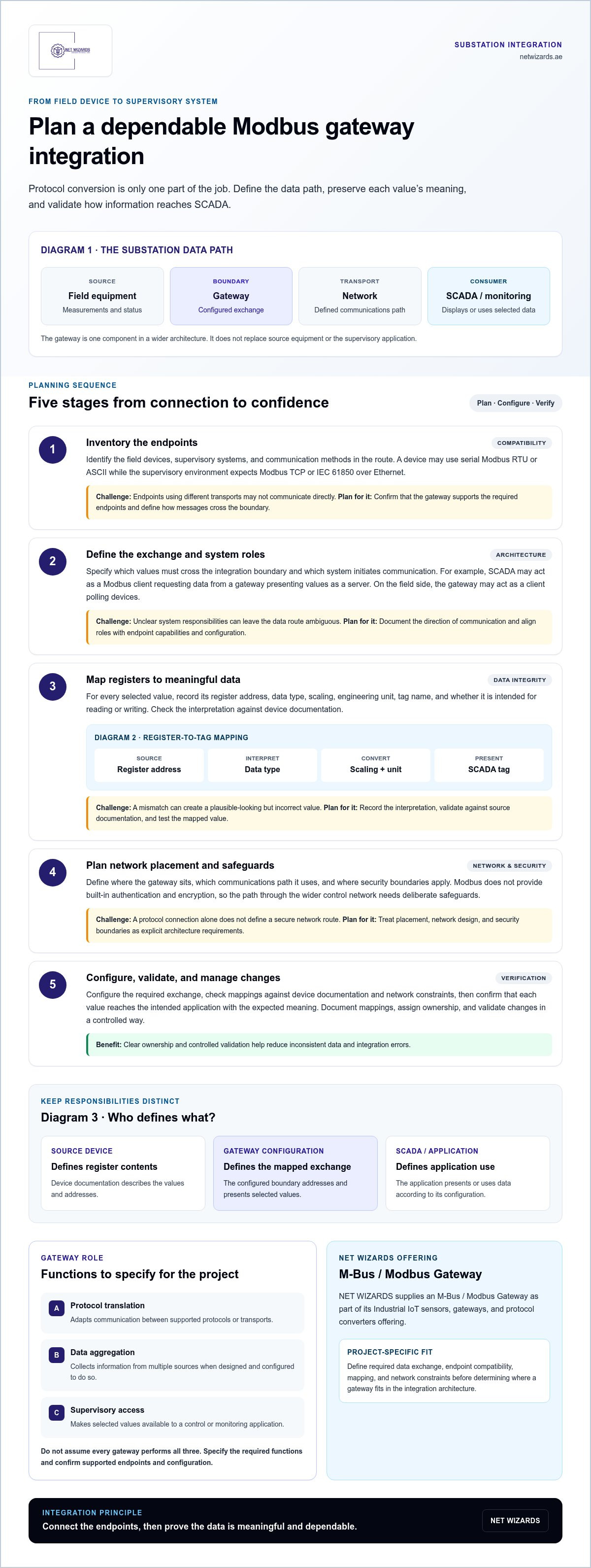
Three related functions are distinct. Protocol translation adapts communication between supported protocols or transports. Data aggregation collects information from multiple sources when the gateway is designed and configured to do so. Supervisory access makes selected values available to a control or monitoring application. Don’t assume every gateway performs all three. Start by defining the data path, then specify the functions the architecture requires.
Diagram 1, substation data path:
Field equipment (data source) → Gateway (integration boundary) → Communications network (transport path) → SCADA or monitoring layer (data consumer)
Where the gateway sits in the substation data path
Field devices provide measurements or status values. The gateway receives selected data and makes it available across a defined boundary, while the communications network carries it to the supervisory system. SCADA or another monitoring application then presents or uses the information according to its configuration. This division clarifies responsibilities: the gateway does not replace source equipment, determine the operational meaning of every value, or take the place of the supervisory application. It is one component in a wider integration architecture, like other industrial protocol converters.
Modbus RTU and Modbus TCP in context
Modbus RTU commonly communicates over a serial connection, while Modbus TCP carries Modbus messages over Ethernet-based networks. Both use the Modbus application protocol, but their transport and connection arrangements differ. A device using one method may not communicate directly with a system expecting the other, so the design must account for how messages cross that boundary. The Modbus protocol overview outlines the protocol’s variants and applications.
For example, a substation may contain an instrument that reports status through serial Modbus RTU, while the monitoring environment expects data over Ethernet. A gateway can provide the conversion when it supports the required endpoints and is configured accordingly. Engineers must still define which values cross the boundary, how the receiving system interprets them, and which communication path the deployment uses. Treat transport compatibility as a design requirement, not an assumption.
How Modbus gateway data moves from substation devices to SCADA
Data reaches SCADA through a configured chain, not through protocol conversion alone. A field device exposes a measurement in Modbus registers. The gateway communicates with that device, applies the project’s defined mapping where supported, and makes the selected value available to a supervisory application. SCADA then reads the value, displays it, or uses it in configured functions.
Each boundary needs clear ownership. The source device defines what its registers contain. The gateway configuration defines how those values are addressed and presented across the integration path. SCADA configuration determines how the received data appears to operators and whether the application uses it for alarms or other functions.
Diagram 2, measurement-to-SCADA flow:
Field device register (device documentation) → Gateway mapping (register address, type, and scaling) → Communications network (network design) → SCADA tag (tag setup and display)
Data mapping and register interpretation
A register map connects device addresses to readable application tags. For example, a device may expose a measurement as a numeric value at a documented register address. The integration design must identify the correct address and interpret the returned data type. If the value needs scaling to represent an engineering unit, define the conversion and unit explicitly rather than relying on an assumption.
Validate the mapping against device documentation and the project design. Confirm the address, data type, scaling, units, tag name, and whether the value is intended for reading or writing. A mismatch can produce a plausible-looking but incorrect value, so record the interpretation and test it against the source. Exact mappings vary by device and application.
Gateway integration with SCADA and other systems
Communication roles depend on the architecture. A SCADA system may act as a Modbus client requesting data from a gateway presenting values as a server. On the field side, the gateway may act as a client when it polls devices. These roles must align with both endpoints’ capabilities and configuration. Before commissioning, define the direction of communication and which system initiates requests.
Keep system responsibilities distinct. The gateway handles the configured exchange at its boundary. SCADA may poll for values and manage operator displays or alarms; a historian stores selected records, while analytics processes data for defined use cases. Those functions belong to their respective applications unless the system design assigns them elsewhere. An industrial protocol converter can support interoperability, but it does not replace correct tag design or application configuration.
For a Modbus TCP-to-RTU integration, document the source and destination roles, register interpretation, and expected data flow. NET WIZARDS supplies an M-Bus / Modbus Gateway for project-specific integration requirements. Discuss gateway integration requirements in relation to the devices and supervisory systems involved.
Substation Modbus gateway challenges and architecture trade-offs
Integration failures often appear as missing, stale, or misleading values rather than a complete loss of communication. A register address may be incorrect, a value may use the wrong data type or scale, or communication settings may not match the device. A substation Modbus gateway also creates a dependency: if it stops exchanging data, downstream systems relying on that path may lose visibility.
Reduce these risks with documented configuration, clear ownership, and a response plan. Assign responsibility for maintaining the register mapping and monitoring communication health. Define how operators and connected applications should behave when values become unavailable. The design should distinguish a communications fault from a valid measurement so stale data is not mistaken for current data.
Common integration failures and their remedies
Check each suspected failure against device and system documentation. Verify settings against the device’s communication requirements and the receiving application’s expectations. Record verified findings and approved changes so commissioning and future maintenance use the same reference.
- Incorrect address: Compare the configured register with the device register map, then test the returned value against the documented point.
- Data interpretation mismatch: Check the data type, scaling, and unit against device documentation and the intended application tag.
- Incompatible communication settings: Compare settings at both endpoints and confirm they match the device and system documentation.
- Unclear configuration ownership: Assign responsibility for maintaining the mapping and record revisions in the project configuration documents.
Validate representative values at the source and receiving application, then document the expected behavior when communication is interrupted. Monitoring requirements should explain how operators distinguish normal updates from unavailable or stale data. Define recovery behavior in the system design, including how communication status is reported and what happens after restoration. Do not assume the gateway provides a particular recovery feature.
Choosing a gateway placement and system boundary
Placing integration closer to field devices can keep the device-facing connection local, while positioning it nearer supervisory infrastructure can simplify access from that side. Neither placement is right for every design. Evaluate maintainability, physical access, network segmentation, access control, and fault isolation within the site architecture. The selected boundary should make responsibilities and permitted communication paths clear.
Assess the impact of gateway failure before finalizing placement. Identify which measurements, statuses, or applications depend on it, then define the operational response if that path becomes unavailable. This failure-impact analysis helps determine whether the affected function needs an alternate operating procedure or another system-level response. Specify and validate requirements for redundancy, firewall functions, and recovery within the overall design rather than treating them as inherent gateway capabilities.
Diagram 3, fault handling:
Normal: Field devices → Gateway → Supervisory monitoring
Fault: Gateway communication interrupted → Affected data marked unavailable or stale → Monitoring or alarm notification as defined by the system → Documented operator response
How to plan and validate a substation Modbus gateway deployment
A reliable deployment starts with requirements and source records, not device configuration. Treat the substation Modbus gateway as one element in the integration design, with defined data consumers, network constraints, and operational ownership. This makes assumptions visible before commissioning and gives the project team a basis for testing the complete data path.
- Inventory the assets. Record each Modbus device, its communication method, available documentation, and required data. Identify the supervisory or monitoring systems that will consume those values.
- Define the integration scope. List required measurements and statuses, identify any permitted commands, and assign ownership for each data mapping. Record network constraints and the intended communication path.
- Prepare the mappings. Use device documentation and register maps to specify addresses, data types, scaling, units, and application names. Mark assumptions that still need validation rather than treating them as confirmed values.
- Configure and test. Apply the approved configuration, then check representative data from the field device through to the consuming application. Test communication loss and restoration according to the system’s planned response.
- Document and hand over. Capture approved changes, test results, responsibilities, and procedures for monitoring and escalation. Keep records usable for future maintenance.
These stages reduce avoidable rework by turning device details and network expectations into verifiable project inputs. When comparing gateway options, use the endpoints, required data exchange, and system boundary defined during planning as your selection criteria.
Pre-deployment information and integration design
Build a working record of device documentation, register maps, communication methods, intended data consumers, and network constraints. For each point, state whether the system will read a value or permit a command, and name the person or team responsible for maintaining its mapping. This preparation helps align configuration with the actual project design before commissioning begins.
Commissioning checks and operational handover
Verify representative measurements against the source device and engineering documentation, then confirm that statuses appear correctly in the intended application. Test the expected response to communication loss and restoration in a controlled commissioning plan. The aim is to validate the design, not to assume uninterrupted operation.
- Confirm values, units, scaling, and status interpretation from source to application.
- Record test outcomes, configuration revisions, assumptions, and approved changes.
- Assign operational monitoring responsibilities and document escalation procedures.
A clear handover gives operators the information they need to recognize data issues and follow the agreed response. NET WIZARDS supplies an M-Bus / Modbus Gateway for project-specific integration architecture.
How NET WIZARDS approaches substation Modbus integration
Select and configure a gateway as part of the complete integration architecture, not as a standalone fix for mismatched devices or unclear data requirements. NET WIZARDS supplies an M-Bus / Modbus Gateway within its Industrial IoT sensors, gateways, and protocol converters offering. The gateway is part of the company’s industrial networking equipment and supports project planning for communication between substation equipment and supervisory systems.
Project requirements shape the integration design. Device protocols, register documentation, required data, network boundaries, and intended applications all determine how a substation Modbus gateway fits into the system. Defining these elements early helps align equipment, mapping, and application configuration while keeping responsibilities clear across the data path.
Gateway capability within a wider integration solution
Gateway hardware can form one boundary in a broader industrial integration architecture. It can support defined data exchange between compatible endpoints, helping supervisory applications receive information in a usable form when the required mapping and system configuration are in place. Better-organized data exchange can support informed operational monitoring and project goals such as operational efficiency, predictive maintenance, energy optimization, and enhanced safety.
Those benefits depend on the whole solution. Accurate source data, documented mappings, appropriate network design, and useful application configuration remain essential. A gateway does not automatically provide analytics, cloud connectivity, or edge computing. Where a wider architecture includes an Industrial-grade IoT Cloud Platform or AI Edge Computing, those functions belong to the relevant system components and need their own design. This distinction keeps product responsibilities and project expectations precise.
Define the next engineering discussion
Before discussing equipment selection or integration scope, assemble a concise project record. Include the devices to be connected, their protocols and communication methods, the required measurements and statuses, the systems that will consume the data, and the planned response to communication faults and recovery. Add available device documentation, register maps, network constraints, and any permitted commands. This gives the engineering discussion a practical basis and helps identify unresolved assumptions.
- Devices and protocols: Identify the source equipment and its communication method.
- Data requirements: List the values, statuses, and any allowed write operations.
- System boundaries: Name the supervisory applications and describe the intended data path.
- Operating needs: Document monitoring expectations, fault response, and mapping ownership.
This information helps NET WIZARDS define the M-Bus / Modbus Gateway’s place in project-specific requirements and integration boundaries. Discuss the architecture with the devices, data, and intended consumers clearly identified to move toward an integration plan grounded in operational needs.
Turn the integration design into a defined project direction
Align engineering, operations, and control-system stakeholders around what the integrated data needs to support. Use the proposed substation Modbus gateway architecture to make decisions about scope, responsibility, and how the system will be assessed after deployment. A shared project direction keeps technical choices connected to operational priorities.
Keep the intended role of each system clear as requirements develop. If devices, data consumers, or operating priorities change, revisit the integration assumptions before extending the design. This provides a disciplined path for future decisions without treating the gateway as a substitute for system-level planning.
NET WIZARDS can discuss the project architecture in the context of its requirements and integration boundaries.
A defined next step gives your team a stronger foundation for progressing the integration with clarity and purpose.
Frequently Asked Questions
What is a substation Modbus gateway?
A substation Modbus gateway is an integration device that exchanges data between compatible Modbus endpoints or between Modbus equipment and another supported system interface. For example, it can provide a defined exchange point between a field device and a supervisory interface. Its function depends on its supported protocols and project configuration. It does not generate the source measurement, make protection decisions, or replace application logic.
How does a Modbus gateway connect substation equipment to SCADA?
It connects equipment and SCADA through an arranged communication path, with each endpoint configured for its role. For instance, a gateway may request data from a field device while SCADA reads the gateway’s exposed values. Engineers should confirm which system initiates communication and verify that the application receives the intended points. Define how the overall system recognizes and handles communication faults.
What is the difference between a Modbus gateway and a protocol converter?
A protocol converter primarily translates communication between supported protocols or transports, while a gateway can describe a broader system boundary for exchanging data. In practice, industrial products may combine or overlap these roles, so the label alone does not establish functionality. For procurement and engineering, compare the required source and destination interfaces with the device’s documented capabilities, then define the project’s expected functions.
Can a Modbus gateway connect Modbus RTU devices to Modbus TCP systems?
Yes, this is a common integration pattern when the gateway supports the required serial-to-Ethernet conversion. For a substation Modbus gateway, confirm that the RTU device and TCP-side system can operate in the intended client and server roles. Use device manuals to establish communication settings, then test representative values through to the supervisory application. A protocol label alone does not prove that a specific device supports the required arrangement.
What information is needed to configure a substation Modbus gateway?
Collect device manuals, communication settings, register maps, data types, units, and the list of points each application needs. Also document whether each point is read-only or permits a command, which system owns its configuration, and any network constraints. For example, a status point used by two applications needs an agreed name and interpretation so each consumer handles the same source data consistently.
What are common causes of Modbus gateway communication problems?
Common causes include an incorrect register address, incompatible communication settings, incomplete point definitions, or incorrect interpretation of a returned value. A disciplined fault check isolates the source device, gateway, network path, and receiving application rather than changing several settings at once. Compare observations with the relevant device and system documentation, then record each verified change to support maintenance and avoid reintroducing resolved faults.
Does a substation Modbus gateway replace a SCADA system?
No. A gateway handles a defined communication or integration role; SCADA provides supervisory functions such as operator displays and, where configured, control. For example, the gateway may make a device value available, while SCADA presents it to an operator or applies its own configured alarm logic. Keep those responsibilities explicit in the design, including which system owns application logic and how operators respond to unavailable data.